Monday 23 January 2017

7 - Segment display with 8051

Now I am going to show "How 7-Segment display with 8051". Here first we know about 7 segment display, In 7-segment there are 8 leds including Decimal point (DP) shown below
Here A-G are 7 leds these are main leds to display 0-9 numbers, another one DP-led. This segment contains 9 pins for 7 pins are assign to 7 leds from A - G, one for Dp and finally the Enable pin. In 7-segment display having enable pin which is either cathode or anode pin. When we use cathode pin it must be connection to Ground-Terminal, if we use anode pin it must be connected to VCC or power supply. 


The above table is very important to run the 7-segment display using any micro-controller. As you seen above table the VALUE-column is full of Hexa-decimal code for each and every number from  0-9.

For Example if you want to display number - 4 we need the value 0x66. If you cascading the two       7 - segments we can display 0-99 numbers and so on.

Code:-  

This code is only for single 7-segment display. It counts from 0-9 and each number is display with some delay.


#include<reg51.h>
# define segment P2                                   // 7-segment is assign to Port-2

void delay(unsigned int ms)                          // Delay function
{
int i,j;
for(i=0;i<ms;i++)
for(j=0;j<1275;j++);
}

void main()                                                    // Main function
{
unsigned char i,array[] = {0x3F,0X06,0X5B,0X4F,0X66,0X6D,0X7D,0X07,0X7F,0X6F};
while(1)
{
for(i=0;i<10;i++)
          {
             segment = array[i];
            delay(100);
             }
       }
}

This is very simple code to execute 0-9 numbers in 7-segment display using 8051 micro-controller.
Here I am using Array, so this post is useful to how to write arrays in Embedded-C.

See the below video to get clarity about "How this code works ?" Thank you


Monday 16 January 2017

How to interface stepper motor to 8051 using Driver

We are already seen that " Stepper motor interfacing with 8051" Click the link to see that post this post is without driver and we also seen that "Stepper motor with driver" Click the link to see that post in this post their is no micro-controller. Now I am Interfacing all these thing in one. What I am going to show is "How to interface stepper motor to 8051 using Driver". In this post we are controlling the driver by using 8051 and we don't need any external clock generator, here one of the pin in 8051 acts as a clock pulse generator. Lets see how it is ?

Now before going to the coding part first we have to get an idea of the code by seeing the Hardware Circuit.


This is the Hardware Circuit. If we start simulation, first the Stepper motor is rotate in Half wave mode in Clockwise direction. Clock pulse is assign to pin P2.4 of 8051, here I use 1 sec time period. If we press the full wave button then Stepper motor starts run in Full wave mode. Similarly If we press the Anti-Clockwise button the stepper motor runs in anti-clockwise direction either in Full wave or Half wave mode. Now we are going to Coding part.

Code :- 

#include <regx51.h>
sbit En=P2^0;                                  // Enable pin is set to P2.0
sbit Rs=P2^1;                                  // Reset pin is set to P2.1
sbit H_F=P2^2;                                // Half / Full pin is set to P2.2
sbit Cw_Ccw=P2^3;                          // Clockwise / Counter CW pin is set to P2.3
sbit Clock=P2^4;                              // Clock pin is set to P2.4
sbit Stop_Button=P1^0;                    // To stop the Stepper motor
sbit F_Button = P1^2;                       // Half wave Button
sbit Ccw_Button = P1^4;                   // Anti Clockwise Button


void delay()                                          // 500ms Delay function using Timers
{
int count=0;
while(count!=500)                              // This loop Counts 500 times
{
       TMOD = 0x01;                              // Timer0 mode1
       TH0 = 0xFC;                                //initial value for 1ms in TH0 and TL0
      TL0 = 0x66;
       TR0 = 1;                                        // To Enable the Timer-0
         while(!TF0);                                 // check overflow condition
            TR0 = 0;                                   // Timer-0 Disable
            TF0 = 0;                                   // Clear flag
count++;
     }
}
 
void clock_pulse()                 // Using Delay we Generate Clock pulse
{
Clock = 1;                           // This clock pulse assign to P2.4
delay();
Clock = 0;
delay();
}

void Stop()                            //  Stop Function
{
   En = 1;                             //To stop the Stepper motor we need this
 Rs = 0;
}

void Half_wave()                   // Half wave function                
{
 clock_pulse();                    // Used to run the S-motor in Half wave mode
H_F = 1;
}

void Full_wave()                    // Full wave function                

 clock_pulse();                    // Used to run the S-motor in Full-wave mode
  H_F = 0;

}
void main()                          // Main Function
{
  En = 0;                           // Initailly all pins set to 0
  Rs = 1;                           // Except Reset pin
  H_F = 0;
  Cw_Ccw = 0;
  while(1)
            {
                if(Stop_Button==0)             // Condition for Stop the S-motor
                          Stop();    
                else if(Ccw_Button==0)       // Condition for S-motor runs in Anti-Clock wise direction
{
                        En = 1;
                          Rs = 1;
                        Cw_Ccw = 0;
                                 if(F_Button==0)         // Condition for Full wave mode
                                        Full_wave();
                                  else
                                        Half_wave();        // Condition for Half wave mode
                        }
                else                        
                 {                                               // Initial this condition is active.
                        En = 1;
                        Rs = 1;              
Cw_Ccw = 1;                          // Used to run S-motor in Clockwise direction
                                  if(F_Button==0)
                                        Full_wave();
                                  else
                                        Half_wave();
                    }

            }

}

See the code carefully this code is very simple to understand. See the below video it shows how it works.


Saturday 14 January 2017

Clock pulse generator using Timers in 8051

In last post we were seeing the Description of Timers and How to calculate the Time delay. So now we can generate clock pulse using the Delay function by using Timers. Before going to that you must read this post Click the link to see that post. Lets do this small concept, first we write the code to generate the clock pulse in 8051.

Code :-

#include<reg51.h>
sbit led=P2^0;
void delay()

{

            TMOD = 0x01;              // Timer0 mode1
            TH0 = 0xFC;                 // Initial value for 1ms in TH0 and TL0
TL0 = 0x66;
            TR0 = 1;                        // To Enable the Timer-0
            while(TF0==0);              // check overflow condition
                        TR0 = 0;                         // Timer-0 Disable 
                        TF0 = 0;                          // Clear flag

}


void main()

{
while(1)
{
led = 1;                            // Led is ON for 1ms
delay();                            // Delay function for 1ms 
led = 0;                            // Led is OFF for 1ms
delay();                            
}
}

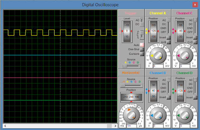
This is the simple code to generate clock pulse. If you execute this code you get this type of result see below. The below figure shows the clock pulse with 1ms ON and  1ms OFF.


Hardware Simulation:-

I run this code in Proteus software, the Hardware circuit is look like this


This clock pulse is play an important role in Embedded systems mainly in Digital circuits. Their is no need to extra circuit to generate clock pulse. They are so many application by applications by using clock pulse I will show in my next few posts.

For clear understanding you see the below video.


Friday 13 January 2017

Delay using Timers in 8051 UC (Description)

In Embedded systems Timers is one of the main concept. These timers are useful to develop a delay functions. Before going to Delay, First of all we known about some registers in 8051 these are used for timers / counters and have different modes of operation. These registers are

TMOD :- Used for Timer Mode of operation as you seen below. Upper nibble (4-bits) for Timer-1                        and lower nibble is for Timer-0.

Gate :- It is used to enable the corresponding Timer. 

Enable or disable the Timer-1 using Gate-1 
            Logic-1 - Timer-1 operates only if INT1 bits is set (P3.3) 
            Logic-0 - Timer-1 operates regardless of the logic state of the INT1. 

C/T :- Counter / Timer. Logic-1 activates Counter and Logic-0 will activate Times. 

M1 & M0 :- This bits are useful to select different modes of operation see the below table.


TCON :- It is useful to control the timer operation. Below image shows the TCON register.


TF1 :-  This bit is set to Logic-1 automatically on the Timer-1 overflow.
TR1 :- This bit is used to enable the timer 1. This pin must be high to enable the Timer-1.
TF0 :- Set to one automatically when Timer-0 overflows.
TR0 :- Place 1 in this bit to enable the Timer-0.

Before going to calculate Delay time we know machine cycle and clock frequency of 8051 mc.

1 Machine Cycle = 12 Clock cycles

In 8051 mc we use crystal oscillator if frequency 11.0592 MHz.

So from this we get
 Frequency = Clock  frequency / 1 Machine Cycle 
                                                         
                                                            = 11.059 MHz / 12
                 
                                                            = 921.6 KHz.
                                       
                                        Time period = 1/ Frequency
                                                           
                                                             = 1/921.6 KHz = 1.085us

Now Calculate the Delay Time period

For Example.  I want time delay = 1ms

Steps:- 
  1. Divide the 5ms with time period i.e   (1ms/1.085us) =  922
  2. Subtraction Value-x from 65536  i.e  (65536 - 922) = 64614  in decimal form
  3. Convert 64614 into Hexa decimal format which gives FC66.
  4. Load this value into TH-0/1 and TL-0/1 i.e TH-0xFC and TL-0x66.
We complete our process these calculations is very useful for coding.

In next post I will show you the virtual mode execution of Delay function using Timers registers in 8051 micro-controller. 

Thursday 12 January 2017

Electronics_Guru: LCD interfacing with 8051-II

Stepper motor with driver

Some of members asked me " How to rotate STEPPER MOTOR continuously with certain angle like 45͒ in any direction like clockwise and anti-clockwise direction. So this type of output we can easily get, only if  stepper motor is interfacing with the driver. This driver is also called controller. The name of that controller is L297. For more details, I can't mention here if you required more details about driver Click this link.

In this post I will show you how to connect stepper motor to this driver. And check how it works as I mentioned above such as clockwise/anticlockwise direction with Full/half wave.

Simply for understanding Full wave means    -- Rotate 90͒  with initial angle of stepper motor.
                                          Half wave means   -- Rotate 45͒  with initial angle of stepper motor.


By simply connect this driver to stepper motor as you seen below for connections


In this simple circuit we want to know about 5-pins of the driver. They are

1. Enable pin                                :- To enable driver, this pin is always in active high

2. Reset pin                                  :- Is used to reset the circuit and brings back to its original state.

3. Half / Full pin                           :- Is used to rotate half angle or full step angle.
                                                         Logic-1 for Half step angle 0-45-90-135-180...
                                                         Logic-0 for Full step angle 0-90-180-270-360...
                                                       
4. Cw/ccw pin                              :- Clock wise / counter clock wise (Anti clock wise) directions.                                                                  This pins helps to move forward or backward.
                                                          Logic-1 Clockwise or forward direction
                                                          Logic-0 Counter clockwise or backward direction.

5. Clock pin                                  :- This pin is used to increase the speed based on your applied                                                                    clock frequencies.


This simple circuit is not work with more effectively in real time so we need to add an extra drive i.e L298 Dual Full-bridge drive, which is used to drive stepper motor runs effectively in real time operation along with L297 driver. If you want to get more details about L298 driver Click this link.

I will show the circuit how to connect the L298 driver to stepper motor along with L297 driver.

  TWO PHASE BIPOLAR STEPPER MOTOR CONTROL CIRCUIT

This circuit is works in real time with more accurate and this help to fast stopping the stepper motor.

See the below video to understand easily and this video shows the different modes in stepper motor as you seen in the datasheet.


Friday 29 July 2016

Stepper motor interfacing with 8051

Now I can show you "How to Interface Stepper motor with 8051 micro-controller using some logic's Click here to see the logic's. I miss two logic's on that link I will give below.


These two logic's are also used when the driver is used.Lets go the programming shown in given below

#include<reg51.h>
sbit w = P2^0;                        
sbit x = P2^1;                           // Motor pins assigned to port 2
sbit y = P2^2;                        
sbit z = P2^3;                        
sbit H = P1^0;                         // Home switch is connected to port 1, pin-0
sbit R_45 = P1^2;                    // Rotate_45 switch is connected to port 1, pin-2
sbit R_90 = P1^4;                                // Rotate_90 switch is connected to port 1, pin-4
sbit R_135 = P1^6;                              // Rotate_135 switch is connected to port 1, pin-6
sbit R_180 = P1^7;                              // Rotate_180 switch is connected to port 1, pin-7

                                                   
void Home()                                //  Motor "Home" function (Starting stage)
{
 w = 0;
 x = 1;
 y = 0;
 z = 1;
}

void Rotate_45()                          // Motor "Rotate 45 degree" function
{
 w = 0;
 x = 1;
 y = 0;
 z = 0;
}

void Rotate_90()                          // Motor "Rotate 90 deg" function
{
 w = 1;
 x = 1;
 y = 0;
 z = 0;
}

void Rotate_135()                         // Motor "Rotate 135 deg" function
{
 w = 1;
 x = 1;
 y = 1;
 z = 0;
}

void Rotate_180()                          // Motor "Rotate 180 degree" function
{
 w = 1;
 x = 0;
 y = 1;
 z = 0;
}

void main()                                         // Main function
{
  H = 0;                                              // Initialize all switches to zero
  R_45 = 0;
  R_90= 0;
  R_135 = 0;
R_180 = 0;
  while(1)
     {
         if(H==1)
             Home();                                
         else if(R_45==1)
             Rotate_45();
         else if(R_90==1)
             Rotate_90();
         else if(R_135==1)
          Rotate_135();
       else if(R_180==1)
          Rotate_180();
         else
             Home();
     }
}

Copy this program into Keil software and create hex file. Next do the same hardware connections  as shown in below using Proteus software.


 If you want detailed description see the below video. See you soon with future updates.


Wednesday 27 July 2016

Uni-polar stepper motor

This post is only useful to know the basics of uni-polar stepper motor. This is very useful basics of uni-polar stepper motor when it is interfaced with micro-controller. And this post only shows the how to control Uni-polar stepper motor logically. If you want to know about step angle of the stepper motor and formula Click this link.

                      Stepper motor having two types one is uni-polar and second one is bi-polar stepper motor. Here I explain about Uni-polar stepper motor. Below diagram  shows the difference between these two stepper motor.

                                   
As you seen in above diagram Uni-polar stepper motor having five terminals namely A, B(A'), C(B), D(B') and final one is connected to Ground terminals. When your connected to micro-controller these four terminals(A, B, C, D) are controlled logically and you get different Step Angles using different logic's. It seems like this


As you seen above figure A, B, C, D terminals are controlled logically by using Micro-controllers.
If logic-0 or logic-1 is applied to all four terminals then angle made by the stepper motor is 0 (Zero) deg. Similarly some logic's are their as shown in below table.


This different logic's will help to get different step angles, when stepper motor is interfacing with micro-controller this logic's are very helpful to get different step angles. I will show you in next post how to interfacing stepper motor with micro-controller using above logic's.